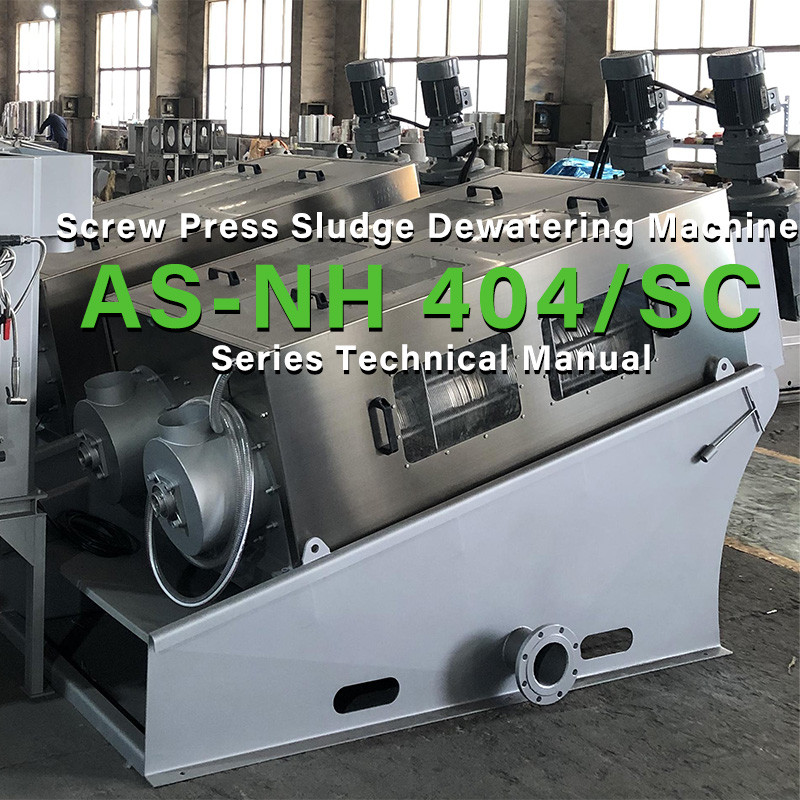
Screw Press Sludge Dewatering Machine AS-NH 404/SC Series Technical Manual
- Share
- publisher
- Kate
- Issue Time
- May 15,2024
Summary
This type of sludge dewatering machine has the characteristics of long service life, small footprint, convenient maintenance, low operating costs, and can realize 24-hour fully automatic operation.
1.1 Technical Introduction
The screw press sludge dewatering machine originated from advanced foreign technology and was later introduced to the domestic market to achieve localization. Over the years, it has been widely applied in the wastewater treatment processes of various industries, serving as a complement to existing domestic technology products. This product features a long service life, compact footprint, easy maintenance, low operating costs, and the ability to operate fully automatically 24 hours a day. Additionally, its ability to handle low concentrations reduces reliance on sludge storage tank concentration tanks) to some extent, saving investment costs for new wastewater projects.
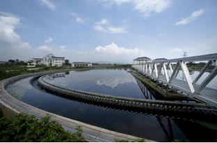
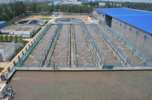
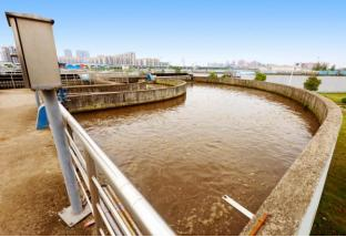
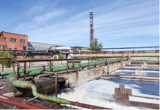
1.2 Application Scope
The screw press sludge dewatering machine has a broad range of applications. It can be used in various industries including oil, municipal, chemical, aquaculture, pharmaceutical, textile dyeing and printing, and mechanical manufacturing. lt can also be partially utilized in the finished products industry.
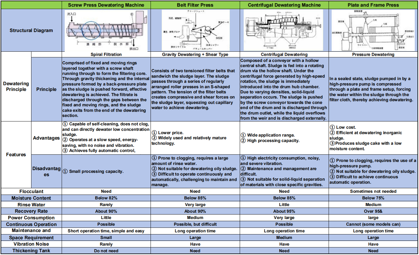
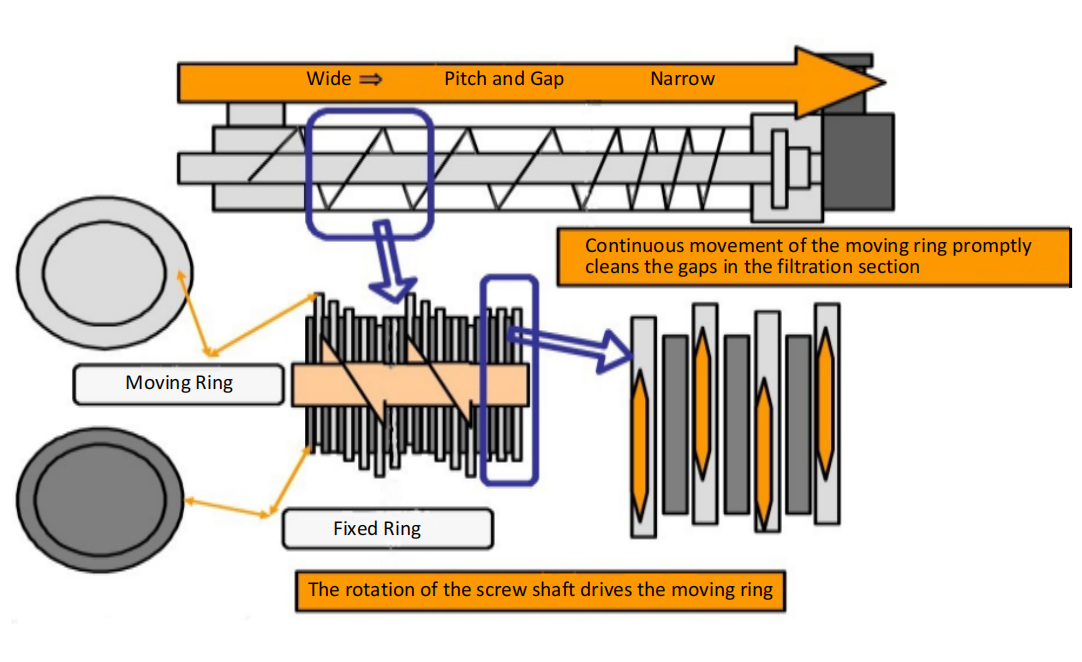
The schematic diagram above shows the main body of the screw press, which consists of fixed rings and moving rings overlapping each other, The front section is for concentration and filtration, while the resection is for extruding the sludge. A screw shaft runs through it, driving the moving rings in the ringpieces to rotate, thus achieving gradual dehydration. The gap along the screw shaft progressively decreases, thereby continuously increasing the pressure within, ultimately ensuring thorough dehydration. This process aims to reduce the moisture content of the sludge. The rotation and pressing of the ring pieces also serve to clean the rings during operation.


3.1 Equipment Data
|
Equipment Model
|
AS-NH 404/SC
|
||
|
Sludge Generation Rate |
~360-600kg/ds/h |
Total Power of Equipment |
9.0kw |
|
Cleaning WaterVolume
|
~200L/H |
Management Frequency
|
5 min/day |
|
Equipment NetWeight
|
~3950kg
|
Operating Weight
|
~5300kg
|
|
Temperature Range |
0℃~+40℃ (Must not freeze) |
Humidity range |
<90%RH |
|
Altitude Range |
Suitable for domestic use
|
Voltage standard |
380V,50/60HZ |
|
Supply water Pressure
|
0.1-0.2Mpa
|
Site requirements
|
Best indoors
|
|
Equipment Model |
EA-404/SC |
Unit Quantity |
1 pcs
|
|
Component Name
|
Specification Parameters
|
||
|
1
|
Total Dimensions of Equipment
|
L4800*W2200*H2100mm
|
|
|
2
|
Total Power of Equipment
|
9kw
|
|
3 | Voltage Standard | 380V.50/60HZ | |
4 | Main Parameters | Size | 400*2650mm |
Quantity | 4 pcs | ||
Material | Main Shaft is made of Stainless Steel(ss304) | ||
5 | Screw Press Motor | Model | EKAF97ER57-Y1.5-4P-505-M4-A-180 |
Waterproof Grade | IP55 | ||
Power | 1.5kw*4 | ||
Note | Motor brand may be changed as per customer requirements or due to supplytimelines, with customer's permission | ||
6 | Flocculation Mixing Tank | Dimensions | L2000*W1000*H1200mm |
Material | SUS304 | ||
Shape | "口"-shaped | ||
7 | Stirring Motor | Model | NMRV75-60-1.5kw |
Waterproof Grade | IP55 | ||
Power | 1.5kw*2 | ||
8 | Solenoid Valve | Model | 2W-20B-AC220V |
Size | DN25 | ||
Material | SUS304 | ||
9 | Level Gauge | Model | HA-3S |
10 | Control Panel | Size | W600*H700*D250mm |
Material | SUS304 | ||
Note | Motor brand may be changed as per customer requirements or due to supplytimelines, with customer's permission | ||
|
Wear Parts |
Material |
Service Life |
|
Moving and Fixed Rings |
SUS304 |
Approximately 17,000 hours (about 2 years) |
|
Main Shaft of Dewatering Machine
|
SUS304 |
Approximately 35,000 hours (about 4 years)
|
|
Note: The timeframes indicated above are approximate. Actual operation times will depend on the sludge and site conditions. |
||
Accessory Equipment List | |||
|
1
|
Medication Pipeline equipped with a y-typ Filter
|
2
|
Outlet equipped with piping and valves
|
3 | Spraying and Cleaning System | 4 | Solenoid Valve |
|
5
|
Level Gauge
|
6
|
Spare Rings (20 sets)
|
|
7
|
Screwdriver, Socket, and other maintenance tools
|
8
|
Operation Manual, Quality inspection Report, Certificate of Conformity, and other
|
|
9
|
Connecting Hoses and Accompanying Electrical Cables, etc.
|
10
|
Filtrate Recovery System
|

6.1 Sludge Pump Selection
The sludge pump continuously transfers sludge from the sludge pool to the dewatering machine without the need for a high-pressure pump. The sludge transfer rate per unit time is calculated based on the maximum processing capacity of the dewatering machine for dry sludge and the actual concentration of the sludge.
Suppose the model is EA-404 with a maximum dry sludge processing capacity of 800 [kg-DS/h] and a sludge concentration of 10,000 [mg/L] (the sludge concentration determines the selection of the sludge pump and should be accurately measured).
Sludge transfer pump capacity = 800 [kg-DS/h] × 1000 [g/kg] ÷ (10,000 [mg/L] ÷ 1000 [mg/g]) = 80 m³/h.
A submersible sewage pump with a capacity of ≤80 cubic meters per hour (with adjustable function) can be chosen. It is advisable to set the height of the sludge dewatering machine higher than the sludge pool to minimize the excess sludge flowing back to the sludge pool due to excessive pump flow. It is recommended to install a valve on the sludge transfer pipe to allow excess sludge to quickly return to the sludge pool.
6.2 Dosing Pump (Metering Pump) Selection
The dosing pump is used to transport the polymer flocculant solution to the flocculation mixing tank of the dewatering machine. The additional amount of polymer flocculant can be calculated based on the dry sludge processing capacity of the dewatering machine, flocculant addition rate, and dilution ratio. The flocculant addition rate is related to the properties of the sludge and the type of flocculant; the ideal floc diameter is 5mm. The dilution ratio can also be adjusted according to actual conditions.
Suppose the model is EA-404 with a capacity of 900 [kg-DS/h], a powder polymer coagulant addition rate of [0.6%], and a dilution ratio of 1000 times. Polymer flocculant pump capacity = 900 [kg-DS/h] × 0.6% × 1000 × 1000 [g/kg] ÷ 60 [min/h] = [50 liters/minute]. It is recommended to choose a 50L/min metering pump
6.3 Dosing System
1. Automatic Dosing Machine (1 set)
Features: Automatically add water and chemicals as long as a sufficient amount of dry flocculant is prepared. The dosing amount is relatively stable, although the equipment is expensive
2. Manual Dosing Barrel (1 set)
Features: Mainly consists of a mixer and a dosing barrel, but it is not easy to operate the equipment unattended for long periods. It can also lead to unstable concentration configurations, causing waste.
The above calculation data is for reference only and should not be used as actual operational data; actual site data should be calculated based on the site conditions.